Brass Electrical Terminals, Neutral Links & Switchgear Components: IEC 60947 & Contact Mechanics
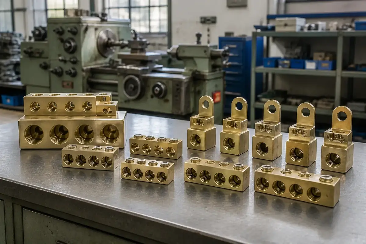
Quick Lookup:
- Specify conductivity, plating, and torque values for switchgear terminals.
- Neutral links and bus connectors need consistent cross-section and finish.
- Tin or nickel plating improves contact reliability and solderability.
- Call out hole patterns, barrier spacing, and applicable IEC/UL norms.
Related reading: tin/nickel plating guide and sourcing brass components.
1. Executive Overview: Jamnagar's Role in Global Power Distribution Infrastructure
In the electrical engineering industry, low-voltage power distribution relies on dependable metallic connections. Every main switchboard, distribution board (DB), miniature circuit breaker (MCB), and electricity meter requires high-conductivity terminal blocks to join incoming feeder cables with outgoing branch circuits.
While pure copper (Cu) offers higher volumetric electrical conductivity (100% IACS), unalloyed copper is too soft and malleable to sustain high mechanical screw clamping torque. Steel screws tightened directly into pure copper threads rapidly strip the internal threads, leading to loose conductor connections, arcing, and electrical fires.
Free-cutting brass (ASTM C36000 / EN CW614N / IS 319 Grade 1) provides the ideal engineering compromise: a continuous electrical conductivity of 26% to 28% IACS, combined with high tensile yield strength (250+ MPa) and high thread hardness (120 - 150 HB). This enables machine shops in Jamnagar to turn multi-hole neutral bars, tunnel terminals, and terminal pins that accept high screw tightening torque (1.2 to 4.0 Ncdotm) without thread stripping or body distortion.
2. Electrical Metallurgy: Conductivity (% IACS), Current Density & Temperature Rise
When designing a brass neutral bar or terminal block, electrical engineers determine the component's minimum cross-sectional area based on continuous current rating (A) and maximum allowable temperature rise (Delta T).
Primary Electrical Parameters for Brass Terminals
- Electrical Conductivity (26% - 28% IACS): Expressed relative to the International Annealed Copper Standard (100% IACS = 58.0 MS/m at 20°C). Free-cutting brass exhibits an electrical conductivity of approximately 15.5 to 16.5 MS/m (resistivity rho approx 0.062 Omegacdotmm²/m).
- Allowable Current Density (Jallow): To prevent excessive Joule heating (P = I² R), turned brass electrical terminals are sized using a continuous current density benchmark of 1.5 to 2.5 A/mm² for natural convection air cooling inside distribution enclosures.
- Temperature Rise Limits (Delta T ≤ 45 K): Under IEC 60947-7-1 standards, when a terminal block carries its full rated continuous current (I_n), the temperature rise at terminal clamping points must not exceed 45 Kelvin above ambient room temperature (20°C - 40°C).
1. Terminal Cross-Sectional Area Formula
Calculate the minimum required net solid brass cross-sectional area (excluding drilled wire hole voids) for a target continuous current:
Anet = fracIratedJallow
- Anet: Minimum Net Solid Cross-Sectional Area (mm²)
- Irated: Maximum Continuous Rated Current (Amperes, A)
- Jallow: Design Current Density (1.8 A/mm² standard for indoor switchgear)
Engineering Example: A 100A main neutral bar operating at J = 2.0 A/mm² requires a net solid cross-sectional area of Anet = 100 / 2.0 = 50 mm². If M6 wire holes are drilled through the bar, the gross bar width and height must be increased to maintain 50 mm² of solid brass metal on either side of the hole.
3. Switchgear Terminal Typology & Component Configurations
Jamnagar contract machine shops turn and mill seven standardized electrical terminal configurations used across global power distribution systems:
| Terminal Category | Geometry & Construction | Conductor Connection Style | Primary Switchgear Application |
|---|---|---|---|
| Multi-Hole Neutral Bars | Extruded rectangular brass bars (6 × 9 mm up to 12 × 20 mm) featuring 4 to 60 cross-drilled wire holes with tapped clamping screw threads. | Direct screw-down pressure on solid or stranded wire | Main distribution boards, consumer units, panelboards |
| Earth Continuity Bars | Multi-tunnel brass bars mounted directly onto panel metal backplates or DIN rails with green/yellow insulator feet. | Direct screw-down or pressure plate clamping | System protective grounding and equipotential bonding |
| Tunnel / Cage Terminals | Hollow square or rectangular turned brass block with internal wire tunnel and heavy clamping screw. | Enclosed tunnel clamping (prevents wire strand splaying) | MCB, RCCB, and MCCB circuit breaker input/output terminals |
| Pillar / Meter Terminals | Cylindrical or square turned brass pillars with dual heavy clamping screws for high-current incoming mains. | Dual screw-down clamping for heavy 25–50 mm² cables | Single-phase and 3-phase smart electricity meters |
| Barrier Terminal Blocks | Turned brass stud contacts or screw-down clamp plates separated by phenolic/polyamide insulating barriers. | Ring or spade crimp lug bolting onto threaded stud | Heavy industrial control wiring and transformer terminals |
| PCB Terminal Pins & Sockets | Precision Swiss-turned solid or hollow brass pins (0.8 mm to 3.0 mm dia) with solder tails. | Through-hole wave soldering onto printed circuit boards | Power electronics, relays, inverter control boards |
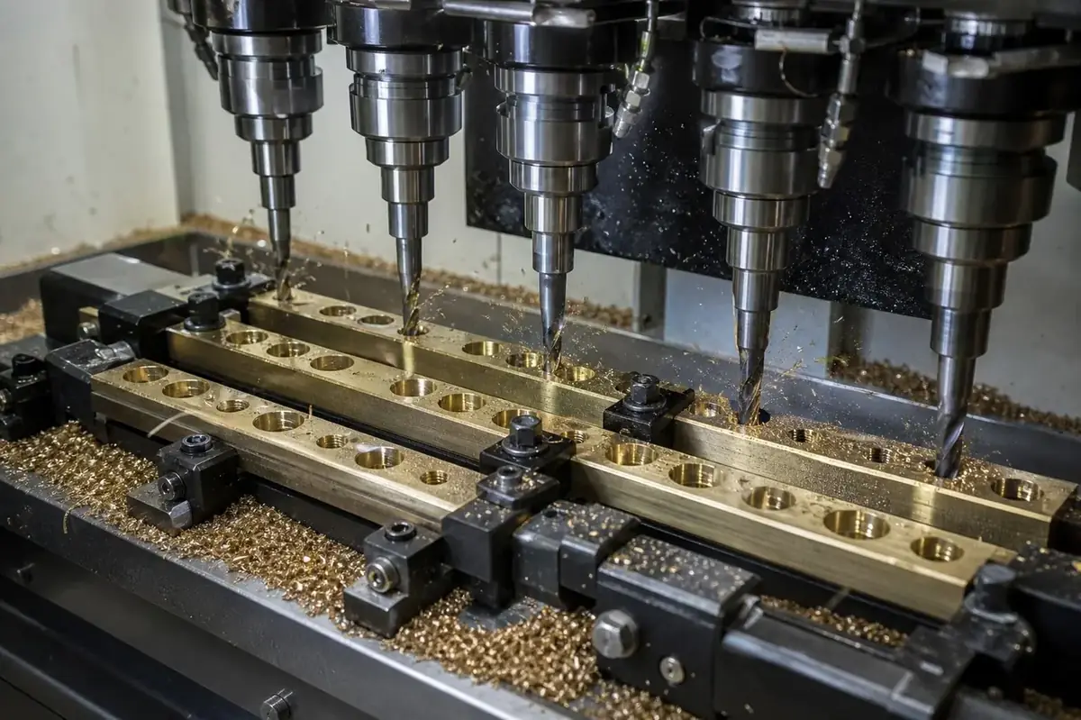
Automated multi-spindle drilling and thread tapping unit in Jamnagar producing 12-hole brass neutral bars from extruded rectangular bar stock.
4. Contact Resistance Mechanics (Rcontact) & Screw Tightening Torque
When a stranded copper cable is clamped inside a brass terminal hole, true electrical contact does not occur across the entire apparent surface area. At a microscopic level, metal surfaces consist of microscopic peaks and valleys (asperities).
Electrical current flows exclusively through microscopic contact spots where asperities physically touch and deform, creating constriction resistance (R_c). Additionally, thin surface oxide or tarnish films create film resistance (R_f).
2. Electrical Contact Resistance Model
Rcontact = R_c + R_f = fracrho₁ + rho₂4 a + R_f propto frac1sqrtFclamp
- Rcontact: Total Electrical Contact Resistance (muOmega)
- R_c: Constriction Resistance at microscopic asperity contact spots
- a: Radius of microscopic contact spot (mm)
- Fclamp: Mechanical Clamping Force applied by the tightening screw (Newtons, N)
Engineering Insight: Increasing mechanical clamping force (Fclamp) plastically deforms microscopic brass-copper contact asperities, enlarging contact spot radii (a), breaking surface oxide films, and reducing contact resistance below 10 muOmega. High contact force prevents local hot-spot thermal runaway!
5. Screw Torque Benchmarks & Anti-Galling Thread Tolerances
To achieve required contact pressure without stripping brass threads or shearing clamping screws, terminal manufacturers specify exact screw tightening torques under IEC 60947-1 Table 4:
| Clamping Screw Size | Conductor Wire Cross-Section Range | Standard Tightening Torque (IEC 60947-1) | Minimum Thread Engagement Length |
|---|---|---|---|
| M3.0 Screw | 1.5 mm² to 2.5 mm² (14–12 AWG) | 0.5 Ncdotm (4.4 in-lbs) | ≥ 1.2 × Screw Dia (3.6 mm) |
| M4.0 Screw | 4.0 mm² to 6.0 mm² (10–8 AWG) | 1.2 Ncdotm (10.6 in-lbs) | ≥ 1.2 × Screw Dia (4.8 mm) |
| M5.0 Screw | 10.0 mm² to 16.0 mm² (6–4 AWG) | 2.0 Ncdotm (17.7 in-lbs) | ≥ 1.2 × Screw Dia (6.0 mm) |
| M6.0 Screw | 25.0 mm² to 35.0 mm² (3–2 AWG) | 2.5 Ncdotm (22.1 in-lbs) | ≥ 1.2 × Screw Dia (7.2 mm) |
| M8.0 Screw | 50.0 mm² to 70.0 mm² (1/0–2/0 AWG) | 6.0 Ncdotm (53.1 in-lbs) | ≥ 1.2 × Screw Dia (9.6 mm) |
6. Surface Plating for Electrical Hardware: Electro-Tin vs. Silver vs. Bare Passivated Brass
Selecting the correct surface finish on turned brass terminals prevents environmental oxidation, reduces contact resistance, and allows clean soldering:
Electro-Tin Plating (5 to 12 Microns) — The Industry Standard
Electro-deposited tin (Sn) is the primary coating for neutral bars, terminal blocks, and circuit breaker contacts. Tin is soft (yielding low contact resistance under screw clamping) and protects copper-zinc brass against atmospheric oxidation. Matte tin (Sn) is specified for PCB pins to prevent "tin whisker" growth, while bright tin provides a clean mirror-silver finish.
Silver Plating (3 to 10 Microns) — High-Voltage & Heavy Current
Electro-plated silver (Ag) provides ultra-low contact resistance for high-current disconnect switches, vacuum circuit breaker contacts, and EV charging station pins. While silver tarnishes in sulfur-rich atmospheres forming silver sulfide (Ag₂S), silver sulfide remains electrically conductive, unlike non-conductive copper oxide verdigris.
Electro-Nickel Plating (3 to 8 Microns) — Corrosive Environments
Nickel (Ni) provides high surface hardness and superior corrosion resistance in chemical plants and marine switchgear. However, nickel has a slightly higher contact resistance than tin or silver; terminal clamping screws must be torqued adequately to break through the nickel oxide surface film.
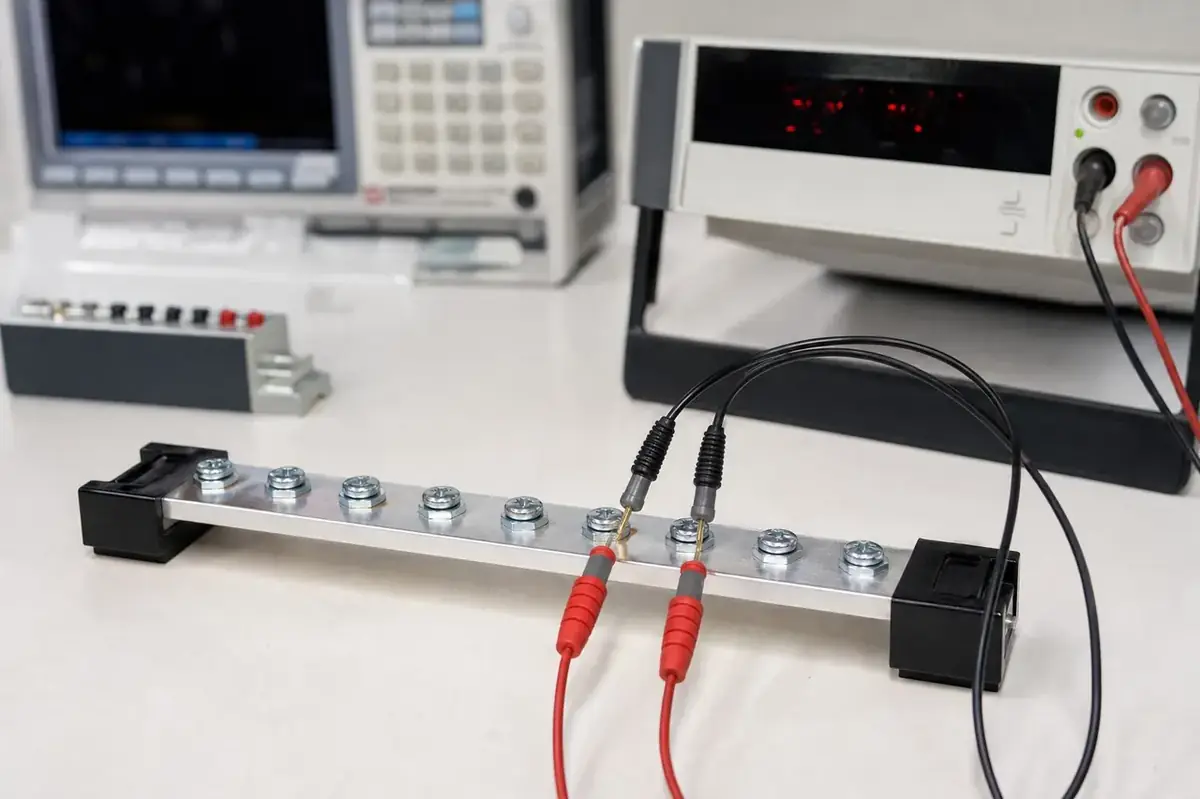
Laboratory four-point micro-ohmmeter testing contact resistance (muOmega) across a tin-plated brass neutral bar under full rated screw clamping force.
7. International Certification & Standards Compliance
To export electrical switchgear assemblies to European and North American markets, turned brass terminals must conform to three international testing frameworks:
Key Switchgear Testing Standards
- IEC 60947-7-1 / EN 60947-7-1: Low-voltage switchgear and controlgear — Terminal blocks for copper conductors. Mandates short-time withstand current tests (120 A/mm² for 1 second), mechanical pull-out tests on clamped wires, and temperature rise verification (Delta T ≤ 45K).
- UL 1059 (Standard for Terminal Blocks): US safety standard evaluating electrical creepage and clearance distances, mechanical torque withstand on brass threads, and dielectric voltage withstand (2,500 VAC for 1 minute).
- BS 7671 (IET Wiring Regulations): UK electrical installation standard governing neutral and earth bar connections in residential consumer units and industrial distribution boards.
8. Printable Quality Inspection Checklist for Electrical Terminals
Quality control teams should enforce this 6-point technical checklist prior to approving brass terminal shipments from Jamnagar:
Raw Material Spectro Audit: Confirm EN 10204 3.1 Spectro report verifies free-cutting brass alloy (Cu 56-59%, Pb 2.0-3.5%, Zn balance) with zero iron inclusion defects (Fe ≤ 0.35%).
Thread Pitch & Depth Audit: Verify 100% of sampled wire clamping screw holes pass Go/No-Go thread plug gauges (Class 6H internal fit).
Over-Torque Thread Stripping Test: Tighten test clamping steel screws to 150% of rated IEC 60947-1 torque to confirm brass threads do not shear or deform.
Wire Tunnel Burr Inspection: Inspect internal wire entry tunnels under optical borescope to ensure zero sharp drilling burrs that could sever fine stranded copper wire filaments.
Plating Micron Test: Verify 5 to 12 mum electro-tin coating thickness via non-destructive XRF coating thickness analyzer.
Contact Resistance Verification: Audit four-point micro-ohmmeter contact resistance across wire clamping joints (≤ 15 muOmega baseline target).
9. Frequently Asked Questions (FAQ)
Q: Why is electro-tin plating recommended for brass neutral bars and switchgear terminals?
Electro-deposited tin (5 to 12 mum) seals bare brass against atmospheric oxidation, reduces electrical contact resistance under mechanical screw clamping pressure, and allows clean lead-free wave soldering on PCB pins.
Q: What minimum thread engagement length is required for steel clamping screws in brass terminals?
To prevent brass thread stripping when tightened to rated torque, the internal tapped thread length must equal at least 1.2 × Screw Diameter (e.g., a minimum of 6.0 mm tapped thread depth for an M5 clamping screw).
Q: Why is brass preferred over pure copper for switchgear terminal blocks and neutral bars?
While copper offers higher electrical conductivity, it is too soft to sustain high mechanical screw clamping torque. Free-cutting brass provides sufficient electrical conductivity (26–28% IACS) combined with high yield strength (250+ MPa) and thread hardness (120-150 HB), preventing thread stripping during installation.
Q: What temperature rise limit is permitted for brass terminal blocks under IEC 60947-7-1?
IEC 60947-7-1 limits the maximum allowable temperature rise (Delta T) at terminal clamping points to ≤ 45 Kelvin above ambient room temperature when operating at full continuous rated current.
Need Custom Turned Brass Electrical Terminals & Neutral Links?
Explore our complete range of multi-hole neutral bars, earth continuity strips, tunnel terminals, meter pillars, and PCB pins available with direct factory net pricing on Jamnagar.net.