Precision CNC Machining & GD&T for Turned Brass: Tolerances, Concentricity & Swiss Lathe Capabilities
Quick Lookup:
- Match geometry to Cam-Automat, fixed CNC, or Swiss sliding-head platforms.
- Baseline linear limits with ISO 2768-m/f where GD&T is not required.
- Apply ASME Y14.5 / ISO 1101 for concentricity, runout, and perpendicularity.
- Hold process capability (e.g. Cpk ≥ 1.33) on critical characteristics.
1. Executive Overview: The Sub-Micron Frontier in Turned Brass Manufacturing
Free-cutting brass (ASTM C36000 / EN CW614N) is universally recognized as the gold standard for high-speed subtractive machining. With a 100% machinability rating, brass allows cutting tool inserts to slice through material cleanly at surface speeds exceeding 300 meters per minute without generating tool-destroying thermal shock or long, stringer chips.
However, as modern OEM designs become increasingly compact and complex, the tolerance band for turned brass hardware has compressed from historical fractions of a millimeter down to single-digit micrometers (mum).
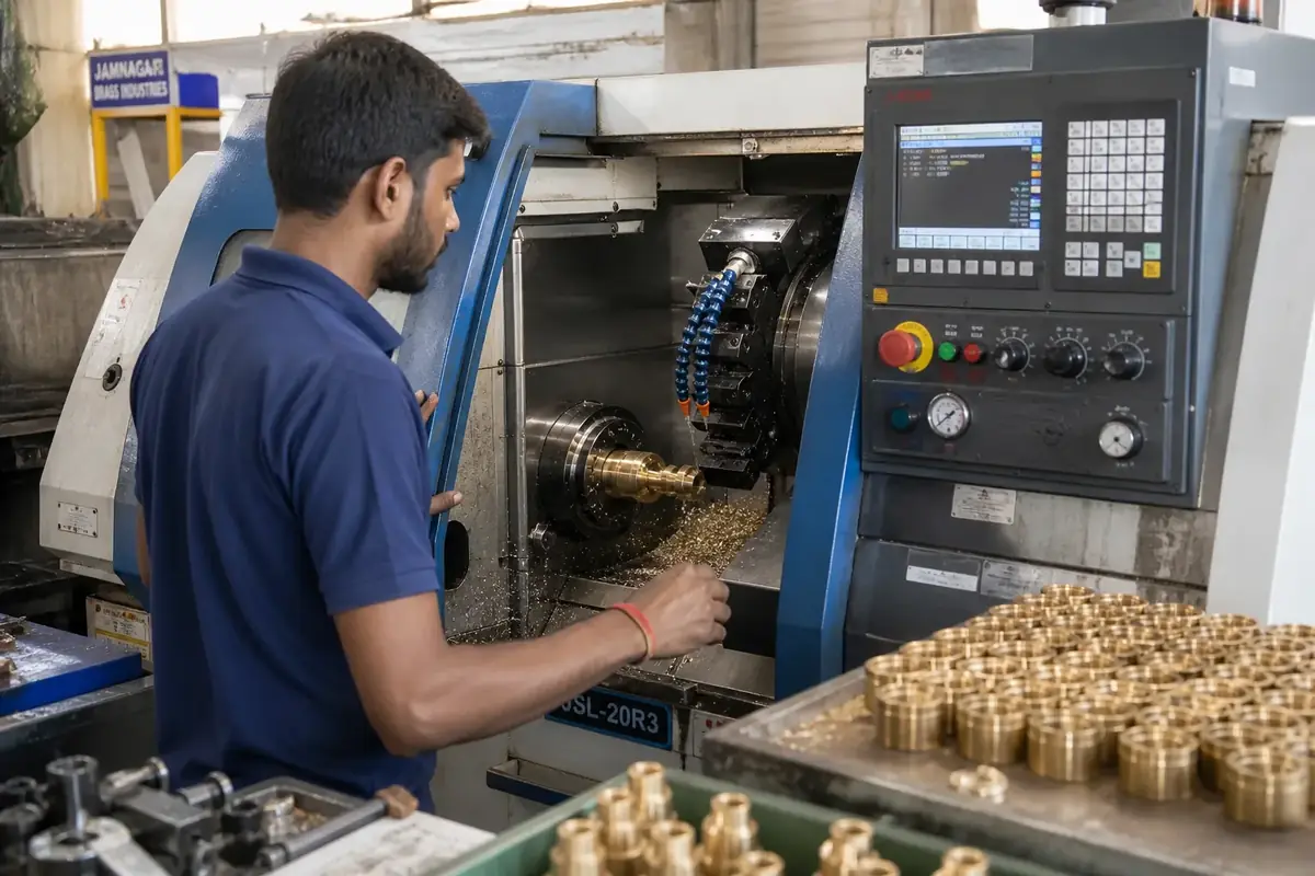
A fuel injection needle valve body, an EV battery cooling port, or a high-frequency coaxial connector pin cannot function if internal bores drift by more than 0.005 mm (5 mum) or if outer diameters exhibit radial runout exceeding 0.010 mm. Jamnagar's advanced machine shops deploy high-precision multi-axis CNC turning centers and multi-channel Swiss sliding-head lathes equipped with thermal displacement compensation, live rotary tooling, and sub-spindles to execute complex multi-operation turned components in a single setup.
2. Machine Tool Capability Comparison: Cam-Automats vs. CNC Lathes vs. Swiss Sliding-Head
Selecting the correct machinery platform in Jamnagar for your production order directly dictates achievable linear tolerances, surface roughness (Ra), and unit cost amortization:
| Operational Attribute | Cam-Driven Automatic Lathe | Fixed-Headstock CNC Turning Center | Swiss Sliding-Head CNC Lathe |
|---|---|---|---|
| Bar Stock Feeding Mechanism | Fixed headstock collet with mechanical bar feed | Fixed headstock chuck/collet with hydraulic bar feeder | Sliding headstock moves bar stock through guide bushing |
| Achievable Linear Tolerances | ± 0.030 mm to ± 0.050 mm | ± 0.010 mm to ± 0.015 mm | ± 0.002 mm to ± 0.005 mm (2 - 5 mum) |
| Length-to-Diameter (L/D) Limits | Max 3:1 without tailstock support | Max 4:1 without tailstock / steady rest | Up to 20:1 without tailstock (Zero Bar Deflection) |
| Live Tooling & Off-Center Milling | None (Turning & axial drilling only) | C-axis + live turret tools (Cross drilling & keyways) | Multi-axis C/Y-axis live tools + Sub-spindle back-working |
| Achievable Surface Finish (Ra) | Ra 1.6 mum - 3.2 mum | Ra 0.8 mum - 1.6 mum | Ra 0.2 mum - 0.4 mum (Micro-Polished Luster) |
| Economic Batch Size Range | 10,000 to 500,000 Pieces | 250 to 10,000 Pieces | 100 to 50,000 High-Precision Pieces |
Why Swiss Sliding-Head Kinematics Eliminate Bar Deflection
In conventional fixed-headstock lathes, the cutting tool moves along the rotating bar stock. As the distance between the chuck collet and tool tip increases, cutting force (F_c) pushes against the unsupported bar, causing mechanical bending and radial chatter.
In a Swiss-type sliding-headstock lathe, the cutting tools remain stationary adjacent to a precision carbide guide bushing. The entire sliding headstock feeds the rotating brass bar forward through the guide bushing directly past the stationary cutting tools. Because cutting forces are supported right at the guide bushing exit point (< 1 mm distance), bar deflection is physically impossible—enabling the turning of long slender pins (L/D ≥ 20:1) to micrometer tolerances!
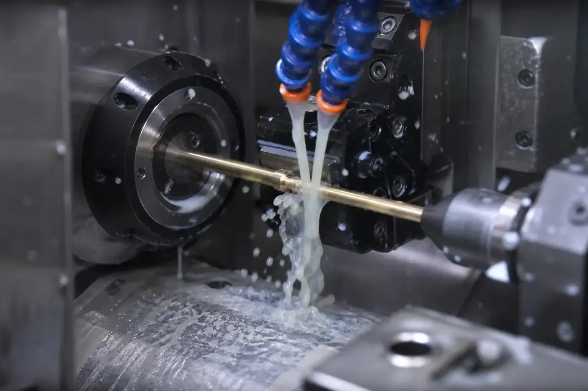
Macro view inside a Swiss sliding-headstock CNC lathe showing a carbide guide bushing supporting a slender turned brass component directly at the cutting zone.
3. Standard Linear Tolerances: ISO 2768-m (Medium) vs. ISO 2768-f (Fine)
When issuing 2D engineering PDF control drawings, stating a universal tolerance standard on the title block eliminates the need to dimension every non-critical feature individually.
International non-ferrous manufacturing recognizes ISO 2768-1 for linear and angular dimensions:
| Nominal Size Range (mm) | ISO 2768-f (Fine Class) | ISO 2768-m (Medium Class — Default) | ISO 2768-c (Coarse Class) |
|---|---|---|---|
| 0.5 to 3.0 mm | ± 0.05 mm | ± 0.10 mm | ± 0.20 mm |
| Over 3 to 6 mm | ± 0.05 mm | ± 0.10 mm | ± 0.30 mm |
| Over 6 to 30 mm | ± 0.10 mm | ± 0.20 mm | ± 0.50 mm |
| Over 30 to 120 mm | ± 0.15 mm | ± 0.30 mm | ± 0.80 mm |
4. Applying GD&T to Turned Brass: Concentricity, Runout & Perpendicularity
Linear plus-minus tolerances (± 0.01 mm) control size, but they do not control form or rotational relationships. For high-speed rotating brass assemblies (pumps, motor commutators, fluid valves, and optical lenses), Geometric Dimensioning & Tolerancing (GD&T under ASME Y14.5 / ISO 1101) is essential.
Jamnagar quality engineers routinely inspect four core geometric controls on turned hardware:
| GD&T Characteristic | ASME Symbol | Engineering Definition | Target Tolerance in Swiss CNC | Primary Function in Turned Assemblies |
|---|---|---|---|---|
| Concentricity | â—Ž | Controls the median points of all diametrically opposed features relative to a primary datum axis. | ≤ 0.005 mm (5 mum) | High-speed balance in motor shafts & turbine nozzles |
| Total Radial Runout | ⌖ / ↗↗ | Controls composite variations in circularity (roundness) and coaxiality across the entire surface length during 360° rotation around datum axis. | ≤ 0.008 mm (8 mum) | Dynamic sealing surfaces & bearing seat journals |
| Perpendicularity | ⟂ | Controls the exact 90° angular relationship of a shoulder face relative to the central turning datum axis. | ≤ 0.005 mm | Flange shoulder sealing against flat O-rings or gaskets |
| Cylindricity | ⌠| Controls roundness and straightness simultaneously, ensuring the entire turned cylinder lies between two concentric virtual cylinders. | ≤ 0.003 mm (3 mum) | Precision hydraulic valve spools & pneumatic pistons |
5. Statistical Process Control: Cpk Capability Indices in High-Volume Runs
When a Jamnagar factory contract-manufactures 100,000 precision turned brass parts, measuring every single dimension manually is impossible. Quality assurance departments rely on Statistical Process Control (SPC) to prove that machine tool variation remains comfortably within the customer's specified upper and lower tolerance limits.
The industry standard metric for process capability is Cpk (Process Capability Index). Cpk measures both how tightly controlled your manufacturing variation is (sigma) and how centered your process mean (mu) is relative to upper and lower specification limits.
Process Capability Index (Cpk) Mathematical Formula
Cpk = min ( fracUSL - mu3sigma, fracmu - LSL3sigma )
- USL: Upper Specification Limit (e.g., 10.005 mm)
- LSL: Lower Specification Limit (e.g., 9.995 mm)
- mu: Sample Mean Average of Production Measurements (mm)
- sigma: Standard Deviation of Production Sample Population
Cpk = 1.00: Process is barely capable (3 Defect PPM or 0.27% scrap rate).
Cpk = 1.33 (Industry Standard Benchmark): Process is capable (64 Defect PPM). Standard for automotive & commercial hardware.
Cpk = 1.67 (Six Sigma Precision): Process is highly capable (0.57 Defect PPM). Mandatory for aerospace & critical medical components.
6. Surface Roughness Mechanics: Ra, Rz, Tooling Inserts & Feed Rates
In fluid handling systems and dynamic O-ring seals, surface roughness is as critical as dimensional tolerance. Excessively rough turned surfaces (Ra > 3.2 mum) shred elastomeric O-rings during hydraulic stroke cycles, causing rapid fluid leaks.
Surface roughness parameter Ra represents the arithmetical mean height of the turned surface profile. Theoretical surface roughness in single-point CNC turning is governed by nose radius (r_varepsilon) and spindle feed rate (f):
Theoretical Surface Roughness (Ra) Formula
R_a ≈ (f² / (32 · rε)) × 1000 (µm)
- f: Feed Rate per Revolution (mm/rev)
- r_varepsilon: Cutting Tool Corner Insert Nose Radius (mm)
Machining Rule: Halving the feed rate (f) reduces surface roughness Ra by a factor of 4! For ultra-smooth sealing journals (Ra 0.4 mum), CNC machinists in Jamnagar combine fine feed rates (f = 0.05 mm/rev), polished Polycrystalline Diamond (PCD) inserts, and high-pressure oil coolant.
7. Metrology & Quality Inspection Laboratory Workflows
Validating sub-micron turned brass hardware requires cleanroom metrology equipment. Jamnagar's advanced quality inspection laboratories deploy three non-contact and contact measurement systems:
1. Non-Contact Optical Profile Projectors & Vision Measurement Systems
High-resolution telecentric optical vision systems magnify turned brass profiles up to 100 times. Automated software measures external diameters, thread pitch angles, chamfers, and groove radii across 50 sample parts simultaneously in under 5 seconds.
2. Pneumatic Air Gauging (Sub-Micron Bore Inspection)
Inspecting tight internal bores (varnothing 3.000 ± 0.002 mm) with mechanical pin gauges can scratch soft brass surfaces. Air gauge plugs emit regulated compressed air; changes in back-pressure directly correlate to bore diameter with sub-micron accuracy (0.5 mum resolution).
3. Bridge-Type Coordinate Measuring Machines (CMM)
3D bridge CMMs equipped with ruby touch-trigger probes verify complex GD&T spatial relationships (concentricity, perpendicularity, true position) against original 3D STEP CAD models in temperature-controlled (20°C ± 0.5°C) metrology labs.
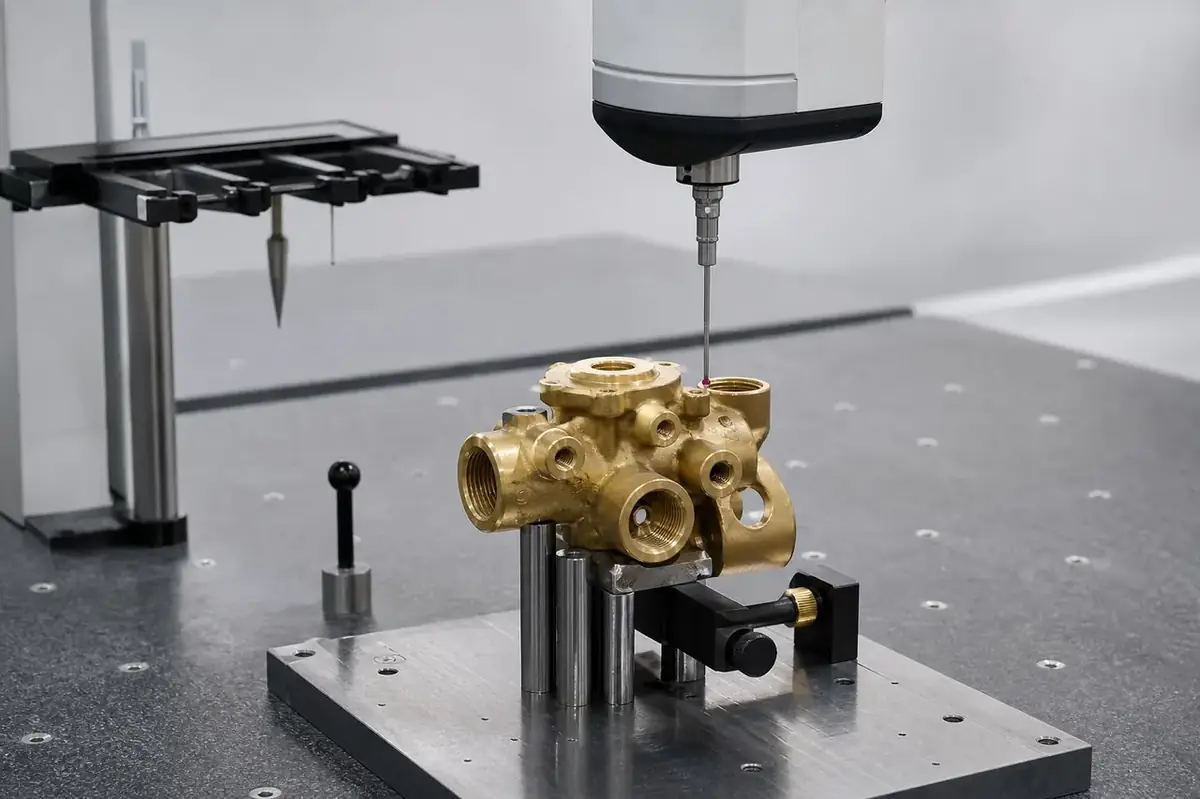
3D Coordinate Measuring Machine (CMM) ruby touch probe validating 5 mum concentricity and perpendicularity on a multi-axis turned brass component in a Jamnagar metrology laboratory.
8. Frequently Asked Questions (FAQ)
Q: What Cpk statistical capability value is required for automotive turned brass components?
Automotive Tier-1 supply chains mandate a minimum Cpk ≥ 1.33 (64 Defect PPM). Critical safety or fuel injection components frequently require Cpk ≥ 1.67 (Six Sigma quality, < 1 Defect PPM).
Q: How does Swiss sliding-head turning allow long slender shafts to be turned without bending?
Swiss lathes feed the rotating bar stock forward through a stationary carbide guide bushing directly past stationary cutting tools. Because cutting forces act within 1 mm of the guide bushing support point, bar deflection is eliminated even on long length-to-diameter ratios (L/D ≥ 20:1).
Q: What is the tightest linear tolerance achievable on Swiss CNC turning centers in Jamnagar?
On multi-channel Swiss sliding-headstock CNC lathes operating in temperature-controlled environments, Jamnagar machine shops achieve linear outer diameter tolerances down to ± 0.002 mm (2 mum) and bore tolerances of ± 0.005 mm.
Q: What is the difference between Concentricity and Total Radial Runout in GD&T?
Concentricity controls only the central median points of diametrically opposed features relative to a datum axis. Total Radial Runout controls circularity (roundness), straightness, and coaxiality simultaneously across the entire surface length during 360° rotation, making runout much easier to measure with dial indicators.
Need Sub-Micron Precision Turned Brass Components?
Submit your complex 2D PDF and 3D STEP CAD files to our direct factory sales desk. Every precision batch produced through Jamnagar.net is metrology-inspected, GD&T verified, and backed by Cpk SPC capability reports on Jamnagar.net.